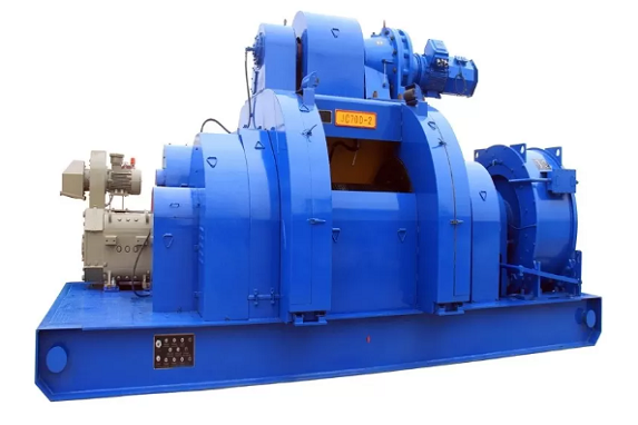
RockySea Petro DrawworksFunction(1) During the drilling process, hang the drilling tools, feed in the drill string and drill bit, and control the drilling pressure.(2) Use the cathead mechanism of the drawworks to tightly unload drilling tools and lift heavy objects.(3) Provide different lifting speeds and weights for drilling operations.(4) As the variable speed mechanism and intermediate transmission mechanism of the turntable.(5) Use the sand drum of the drawworks to perform core extraction,
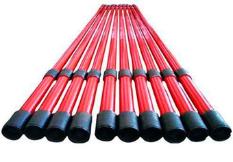
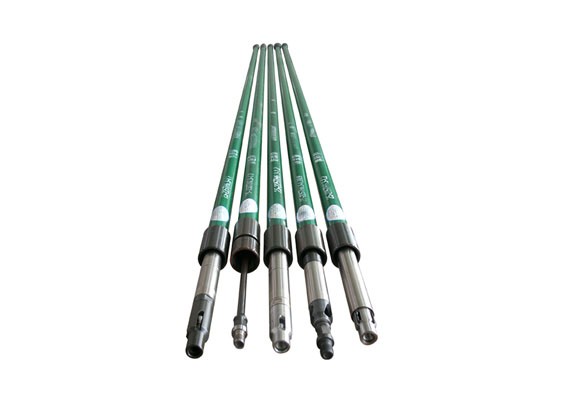
VIEW DETAILSRockySea Petro Rod PumpThe raw material of rod pump parts should be inspected after heat treatment, the mechanical properties, chemical compositions and metallographic structures must be inspected by batch. The rod pump parts should be inspected several times during the processing procedure. Some key points like the outer diameter of the plunger and the inner diameter of the pump barrel should be 100% inspected.Your Best Pump ManufacturersSealing performance tests must be carried out 100% after fini
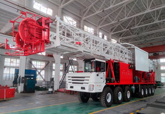
VIEW DETAILSRockySea Petro Self-Propelled Carrier and TralierFeaturesRockySea Petro has developed a special workover rig chassis range from 6X6 to 14X14, which is compatible with the entire series of XJ250 to XJ850 workover machines. It can operate in various terrains such as roads, deserts, mountains, and swamps, with strong driving power, good off-road performance, and can work in the range of ambient temperature -45 ℃ to 50 ℃.Besides,the company also developed a desert off-road carrier. The driving type is
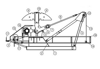
VIEW DETAILSRockySea Petro Low Profile Pumping UnitLow Profile Nodding DonkeyBeam Balanced Pump JackRM Beam Pump(ReversMark Beam Pump)Conventionalpumping unitRockySea Petro Petro has a strong pumping unit design ability. According to International Standard and China national standard, SanJack Petro has designed and developed a series of pumping units according to market demand.Description Low profile pumping unit is designed for applications where pump height is a critical concern. For locations with overhead irr
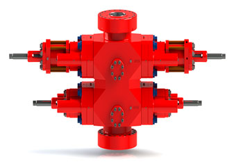
VIEW DETAILSRockySea Petro Cameron U And C Ram BOPAll BOP will receive rigorous tests, such as magnetic particle, ultrasonic, pressure test and so on.AutoCAD and Solid Works computer software are used for drawing design. Also virtual prototype technology is used for simulation and verification of strength.RockySea Petro has been certified by ISO9001, ISO 14001 standard.RockySea Petro Petro owns a strong ability about research, design and manufacture, of Blowout preventer. The company can supply Cameron U and C ram BOP which
VIEW DETAILS
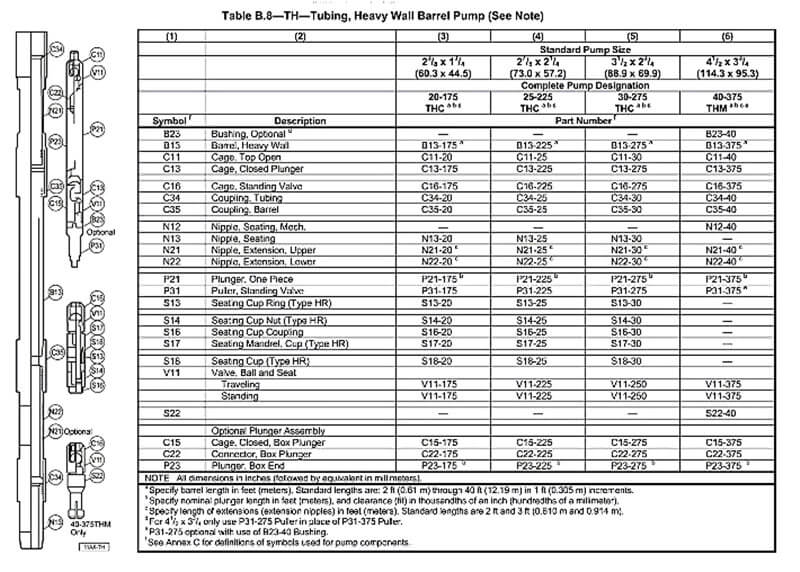
| Pump code | 25-106TH | 25-125TH | 25-150TH | 25-175TH | 25-200TH | 25-225TH | 30-250TH | 30-275TH | 40-325TH | 40-375TH |
| Basic pump diameter | 1 1/16 | 1 1/4 | 1 1/2 | 1 3/4 | 2 | 2 1/4 | 2 1/2 | 2 3/4 | 3 1/4 | 3 3/4 |
| (27.00) | (31.8) | (31.8) | (44.5) | (50.8) | (57.2) | (63.5) | (69.9) | (82.6) | (95.3) | |
| Plunger length | ≤26(7925) | |||||||||
| Pump barrel length | ≤34(10363) | |||||||||
| Stroke ft (mm) | ≤32(9754) | |||||||||
| Connecting tubing thread | 2 7/8 NU(EU) | 3 1/2 NU(EU) | 4NU | 4EU | ||||||
| Connecting sucker rod thread | 3/4 in | 7/8 in | 1 in | |||||||
| Theoretical displacement | 0.824 sn | 1.140 sn | 1.642 sn | 2.235 sn | 2.918 sn | 3.694sn | 4.560 sn | 5.518 sn | 7.707 sn | 10.261 sn |
| Maximum outer diameter (mm) | 3.5 | 3.5 | 3.5 | 3.5 | 3.5 | 3.5 | 4.25 | 4.25 | 4.5 | 4.6 |
| (88.9) | (88.9) | (88.9) | (88.9) | (88.9) | (88.9) | (108) | (108) | (114.3) | (117) | |
RockySea Petro Copyright © 2008-2025 Inc. SITEMAP